

What is xj-scanner?
xj-scanner connects a laptop to the engine computer in a 1991–95 Jeep using an inexpensive 5 V Arduino Nano. Three wires run from the diagnostic connector under the hood to the Nano, which connects to the laptop over USB.
Once connected, the project can read fault codes and live engine data, log information during a drive, and run the engine computer’s built-in actuator tests. Claude Code, Codex, or another coding agent can guide you through setup and interpret the repository’s instructions.
The project was built and tested on a 1994 Jeep Cherokee XJ with a 4.0L engine and computer part number 56030117. Other 1991–95 Chrysler and Jeep SBEC/OBD1 computers may be similar, but compatibility is not guaranteed. Always measure your own diagnostic connector before attaching hardware.
Key features
- Reads engine-computer fault codes.
- Displays live engine parameters and their scaled values.
- Logs live data to files under
pc/logs/. - Supports the engine computer’s built-in actuator tests.
- Includes a simulated Jeep mode for testing the laptop software without a vehicle.
- Provides a Nano wiring-debug sketch as well as the main bridge firmware.
- Includes helper tools for summarizing logs, sweeping parameters, and checking the computer part number.
- Provides agent-oriented playbooks for guided installation and troubleshooting.
Hardware you need
The expected hardware cost is about $15. Gather the following components before starting:
- A 5 V Arduino Nano clone with USB-C or mini-USB and a matching cable.
- A small breadboard.
- A few breadboard jumper wires.
- Three wires long enough to reach from the under-hood connector to the laptop location.
- Three 1/4-inch male spade terminals that fit into the diagnostic connector.
- A multimeter.
Critical safety warning
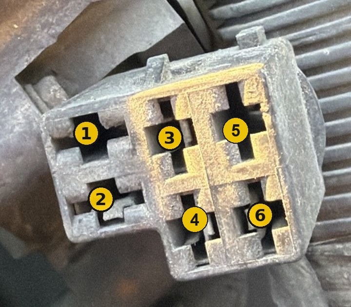
Cavity 6 carries 12 volts when the ignition key is on. Never connect the Arduino or any scanner wire to cavity 6.
Do not identify connector cavities by wire color. On the test vehicle, cavity 6 used the same black-and-white wire color as the ground wire. A mistaken connection could expose the Nano or laptop to vehicle voltage.
Before wiring anything, use a multimeter to check every cavity. Compare your measurements with the expected readings in docs/connector.md. The repository’s tested wiring connects Nano pins D10, D11, and GND to diagnostic-plug cavities 4, 3, and 2 respectively, but you must verify the connector on your vehicle first.
Option 1: Let an AI coding agent guide the setup
The easiest installation path is to use Claude Code, Codex, or another repository-aware coding agent.
- Clone the xj-scanner repository to your laptop.
- Open the repository in your coding agent.
- Ask: Help me hook this up to my Jeep.
- Follow the instructions one step at a time.
The agent can read AGENTS.md and the playbooks under .claude/skills/. These instructions cover software setup, breadboard assembly, identifying connector cavities with a meter, and taking the first reading. If an instruction is unclear, ask the agent to explain it in simpler terms before proceeding.
Option 2: Install and run xj-scanner manually
1. Create the Python environment
From the repository root, create a virtual environment and install the scanner’s dependencies:
python3 -m venv .venv && .venv/bin/pip install -r pc/requirements.txt2. Test the laptop software in demo mode
Before connecting to the Jeep, run the scanner against its simulated vehicle:
.venv/bin/python pc/xj_scan.py --cli DEMOThis confirms that the Python side works without requiring an Arduino or engine computer. If demo mode fails, resolve the laptop-side issue before moving on to vehicle wiring.
3. Install Arduino CLI and the AVR core
The README provides the following commands for macOS with Homebrew:
brew install arduino-cli
arduino-cli core install arduino:avr
If you use another operating system, install arduino-cli using the appropriate method for that platform, then install the arduino:avr core.
4. Connect and identify the Nano
Attach the Arduino Nano to the laptop over USB. Determine its serial port, then replace /dev/cu.usbserial-XXXX in the upload command with the actual port.
The example uses the board identifier arduino:avr:nano:cpu=atmega328old, which selects the old bootloader configuration used by many Nano clones.
5. Compile and upload the bridge firmware
arduino-cli compile --upload -p /dev/cu.usbserial-XXXX --fqbn arduino:avr:nano:cpu=atmega328old arduino/xj_bridgeThe xj_bridge sketch turns the Nano into the communication bridge between the laptop scanner and the Jeep engine computer.
6. Verify and assemble the wiring
With the vehicle wiring disconnected from the Nano, use the multimeter to identify the diagnostic connector cavities. Consult the repository’s docs/ directory for the connector measurements, breadboard layout, and wiring details.
For the tested vehicle, the three signal connections are:
- Nano
D10to diagnostic connector cavity4. - Nano
D11to diagnostic connector cavity3. - Nano
GNDto diagnostic connector cavity2.
Do not proceed based only on this list. Verify each cavity on your vehicle and keep all wires away from cavity 6.
7. Read fault codes and live data
Once the firmware and verified wiring are ready, turn the ignition key to ON and run:
.venv/bin/python pc/xj_scan.py --cli autoIn automatic mode, the scanner reads fault codes and then collects live data. Logs are written under pc/logs/.
Understanding the repository layout
arduino/: Contains the mainxj_bridgeNano sketch and thexj_sniffwiring-debug sketch.pc/: Containsxj_scan.py, which handles fault codes, live data, logging, and actuator tests.tools/: Contains utilities for summarizing logs, sweeping every parameter, and checking the engine computer’s part number.docs/: Documents the connector, wiring, communication protocol, parameters, scaling formulas, and troubleshooting procedures..claude/skills/: Contains step-by-step playbooks that an AI agent can follow with you.
Basic workflow
A cautious first session should follow this order:
- Run
DEMOmode to validate Python and its dependencies. - Upload
xj_bridgeto the Nano. - Disconnect vehicle-side wiring and measure every connector cavity.
- Confirm ground and communication cavities using the documentation.
- Build the breadboard circuit and recheck every connection.
- Turn the key to ON without starting the engine.
- Run the scanner with
--cli auto. - Review the reported fault codes and confirm that a log appears in
pc/logs/.
Advanced tips
Use the debug sketch when communication fails
The arduino/xj_sniff sketch is included for wiring diagnostics. Use it together with the troubleshooting material in docs/ when the bridge cannot communicate with the engine computer. Avoid changing wiring while it is energized.
Summarize drive logs
After recording live data, inspect the helpers under tools/. The repository includes a log-summary utility that can make a long recording easier to review. Work from a copied log if you want to preserve the original data unchanged.
Sweep available parameters carefully
A helper tool can sweep every parameter known to the project. Consult the protocol and parameter documentation before using it so you understand what is being requested and how each raw value is scaled.
Check the engine computer part number
Because the project was validated on engine computer 56030117, use the provided part-number helper when investigating another vehicle. A different SBEC/OBD1 computer may behave similarly, but the README does not guarantee support.
Be cautious with actuator tests
The PC scanner supports built-in actuator tests. These tests can command vehicle hardware, so run them only when you understand the specific test, the vehicle is safely positioned, and moving or energized components cannot cause injury or damage.
Use the detailed scaling documentation
The docs/ directory describes the available parameters and scaling formulas. Refer to it when interpreting raw readings, especially if you are analyzing fuel trim or comparing a value against another scan tool.
Troubleshooting checklist
- Confirm that
--cli DEMOworks before diagnosing the vehicle connection. - Verify that the Nano appears on the expected USB serial port.
- Confirm that the firmware was uploaded with the correct Nano bootloader selection.
- Measure the diagnostic connector instead of relying on wire colors.
- Ensure no wire is connected to cavity 6.
- Check the D10, D11, and GND breadboard paths against the wiring documentation.
- Use
xj_sniffand the troubleshooting guide when the electrical setup appears correct but communication still fails. - Remember that untested Chrysler or Jeep computers may differ from the 1994 Cherokee test vehicle.
Conclusion
xj-scanner provides a low-cost way to explore a compatible Jeep’s OBD1 engine computer with a laptop and Arduino Nano. Start with demo mode, verify every connector cavity with a multimeter, and follow the repository documentation closely. The project is GPLv3 hobby software that communicates with vehicle electronics, so use it at your own risk and treat electrical safety as the first priority.
The project builds on protocol, parameter, scaling, and fault-code work from ChryslerScanner, with fuel-trim scaling informed by disassembled SBEC code.